For this section we HIGHLY recommend you put the names you create in the Naming Conventions sheet.
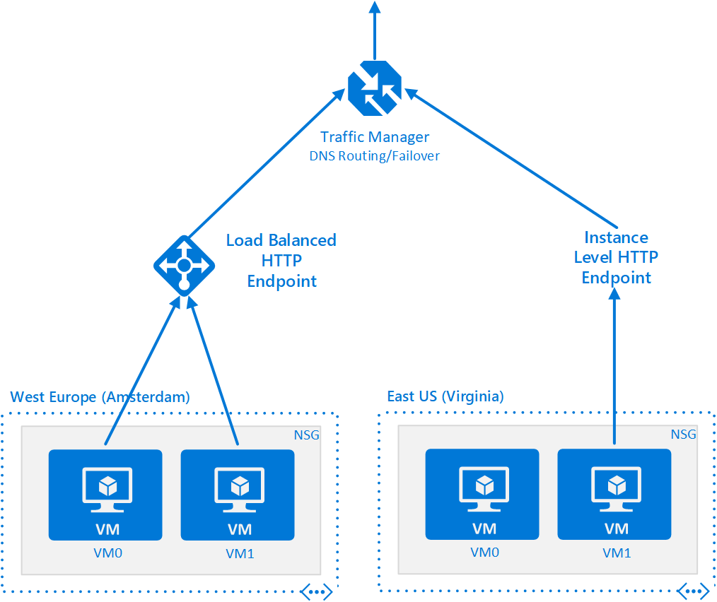
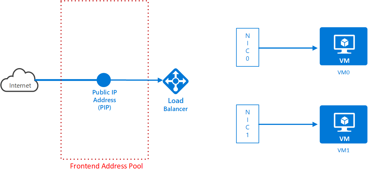
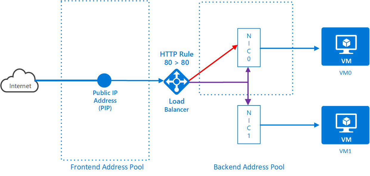
You’ll start with a PIP and add more resources to eventually connect the PIP through a load balancer to your VMs in Amsterdam. Here’s a diagram of what you’ll eventually achieve:
-
Open Command Prompt and login to the Azure CLI with the following command:
az login -
Firstly, create a PIP called <loadbalanced pip name> in your resource group in the West Europe region. The diagram shows the PIP is not yet connected to your VMs. NOTE: In the diagrams that follow, as each new resource is added, IT APPEARS IN RED.
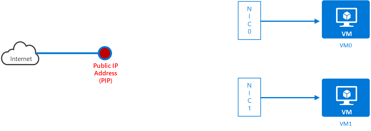
Set the DNS name to <load balancer pip DNS name> (…so mine would be called “dnsamslbpipbemcgarry” and this would result in a FQDN of “dnsamslbpipbemcgarry”.westeurope.cloudapp.azure.com).
Set an address allocation type of “static”. This means you get to keep the public IP address permanently. The other option is “dynamic” where the address could change. The DNS name-IP mapping will always work correctly so DNS names will be reliable.
Static allocations are useful for apps that require fixed IP addresses. To get help for the command in this example type
az network lb create -h. The command for this is below. Remember you are focused on Amsterdam so use the correct names from the table.az network public-ip create -g <resource group name> -n <load balancer pip name> -l westeurope --dns-name <load balancer pip DNS name> --allocation-method static -
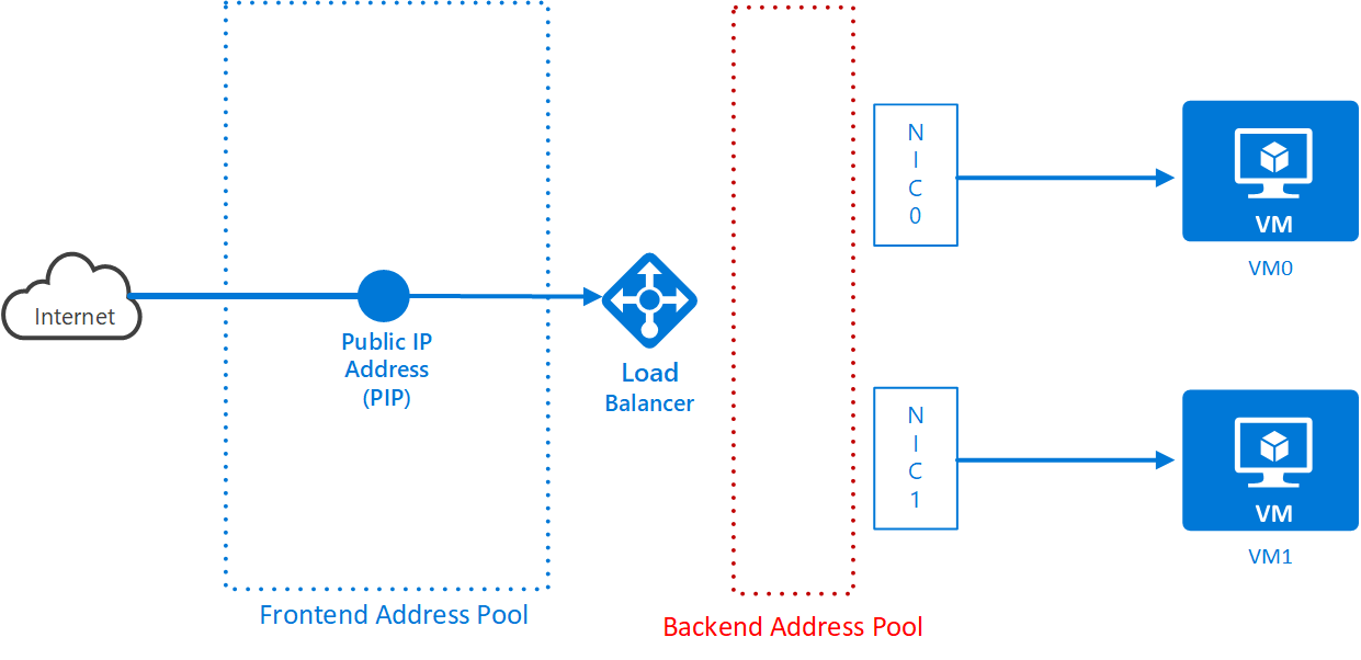
Create a Load Balancer called <load balancer name> in your resource group in the West Europe region. The diagram looks like this:
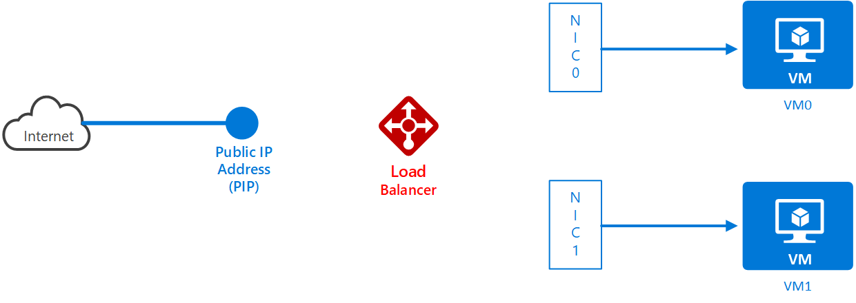
Notice I use “West Europe” (in quotes). You can alternatively use westeurope (without spaces or quotes):
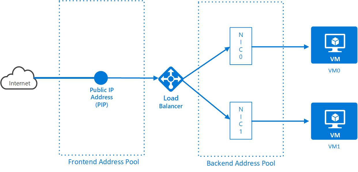
az network lb create -g <resource group name> -n <load balancer name> -l "West Europe" --backend-pool-name <backend pool name> --frontend-ip-name <frontend config name> --public-ip-address <load balancer pip name>The load balancer has inputs, where the traffic comes from and outputs where the traffic goes to. These are known as frontend config and backend address pool. In this exercise, the PIP is associated with the front end address pool (this guarantees the traffic comes from the Internet). The diagram shows this:
-
The load balancer is associated with a backend pool. You also need VMs (or more accurately, NICs) associated with the backend pool, but that comes later. You created a backend pool when you set up the load balancer.
-
The load balancer needs to check that the VMs it is passing traffic to are alive. It does this by sending data to the machines regularly. It expects a response. If it gets nothing back, then it knows the VM is dead and it will take it out of circulation and stop sending traffic to it. It’s a requirement that you create a health probe to do this and associate it with the load balancer.
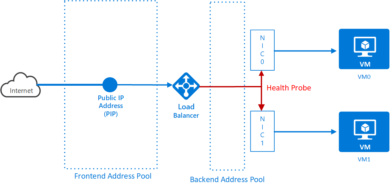
Create a Health Probe in your resource group attached to your load balancer. Name the probe <health probe name>. Use
az network lb probe create -hto see what all the command line switches mean.az network lb probe create -g <resource group name> --lb-name <load balancer name> -n <health probe name> --protocol tcp --port 80 --interval 15 --threshold 4 -
The load balancer will pass traffic from the frontend pool to the backend pool. It needs to know which protocols and ports are being load-balanced between the 2 pools. In this case, you need to load balance traffic from the frontend on port 80 to the backend on port 80.
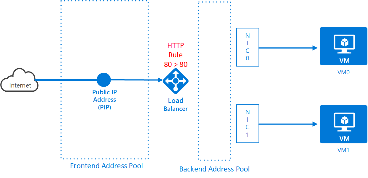
az network lb rule create -g <resource group name> --lb-name <load balancer name> -n <load balancer rule name> --protocol tcp --frontend-port 80 --backend-port 80 --frontend-ip-name <frontend config name> --backend-pool-name <backend pool name> --probe-name <health probe name> -
Use the portal to find and note the name of the first NIC. Now associate the first NIC with the backend address pool:
az network nic ip-config address-pool add --address-pool <backend pool name> --ip-config-name ipconfig1 --lb-name <load balancer name> -g <resource group name> --nic-name <1st NIC name> -
Use the portal to find and note the name of the second NIC. Now associate the second NIC with the backend address pool:
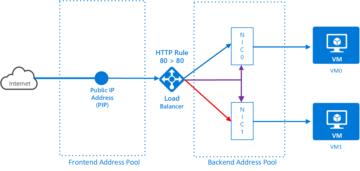
az network nic ip-config address-pool add --address-pool <backend pool name> --ip-config-name ipconfig1 --lb-name <load balancer name> -g <resource group name> --nic-name <2nd NIC name> -
Test the load balancing features out. Open a browser and go to <load balancer pip DNS name>.westeurope.cloudapp.azure.com. The load balancer may take a few minutes to respond after initial setup.
By refreshing the browser several times using Ctrl+F5 you should see it load balance between the 2 web servers you created. If you can’t get it to work (the load balancer can be “sticky” in some cases), work with a neighbour and get them to connect to your endpoint to prove that the load balancer is balancing load. You could even return the favour to your neighbour if he/she is having equal difficulty.
Summary so far
You now have 2 load balanced VMs running in Amsterdam each running a webserver. You have 2 VMs running in Virginia but only one of them has a web server at the moment and it has its own instance-level PIP/DNS name:
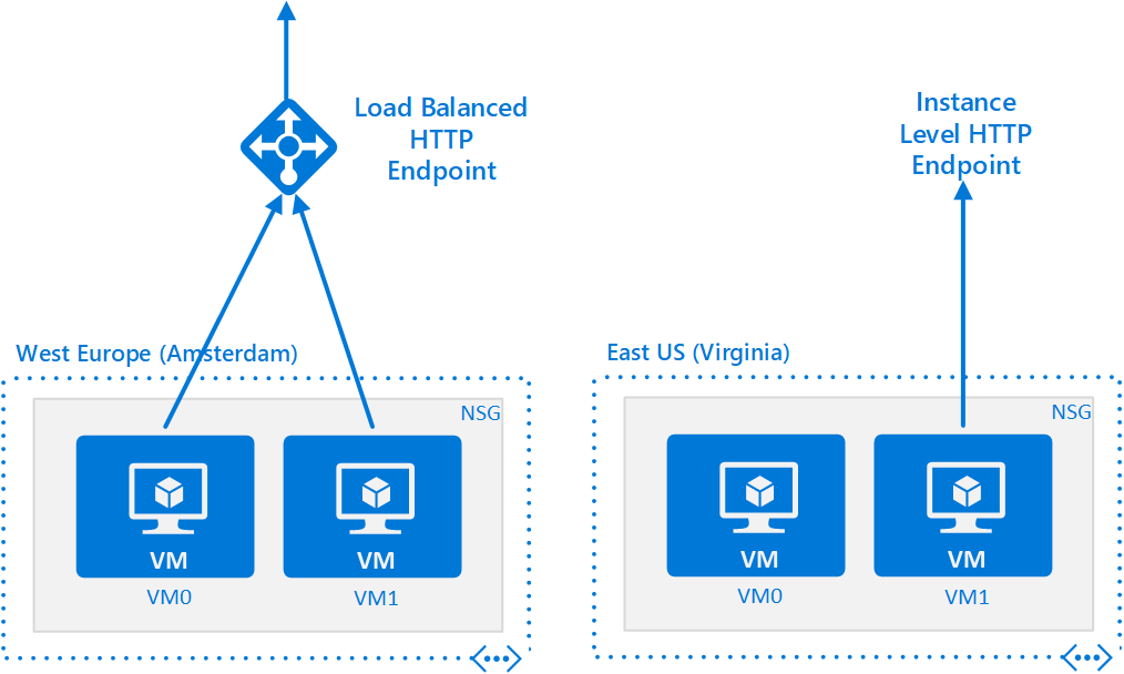
Your next task is to provide failover across geographies (Amsterdam-to-Virginia) using Azure’s DNS infrastructure called Azure Traffic Manager.